Schematic Design
Learn to design the circuit for a 555 LED Chaser. We'll be using EasyEDA Standard Edition.
Creating your project
Go to easyeda.com/editor and click Design Online > STD edition. We are using the standard edition for simplicity.
Once the editor loads, click File > New > Project. Name your project (e.g., "555_Chaser") and click Save.
The Component Library
In order to place components, click Library on the left sidebar and search for these specific part numbers. Click "Place" for each one:
| Part Code | Component Description |
|---|---|
| CD4017BCN | Main CD4017 IC |
| C46749 | 555 Timer IC |
| C492401 | Power Header (VCC/GND) |
| C81276 | Debug Header |
| C62934 | Electrolytic Capacitor (Directional!) |
| C249157 | Ceramic Capacitor |
| C713997 | 1k ohm Resistor |
| C58592 | 470 ohm Resistor |
| C118912 | Potentiometer (Speed Control) |
| C2895480 | Normal LED (Place 10) |
Placement & Arrangement
Now that you have placed all of your components, arrange them approximately as shown below. This will make it much easier when you wire the circuit.
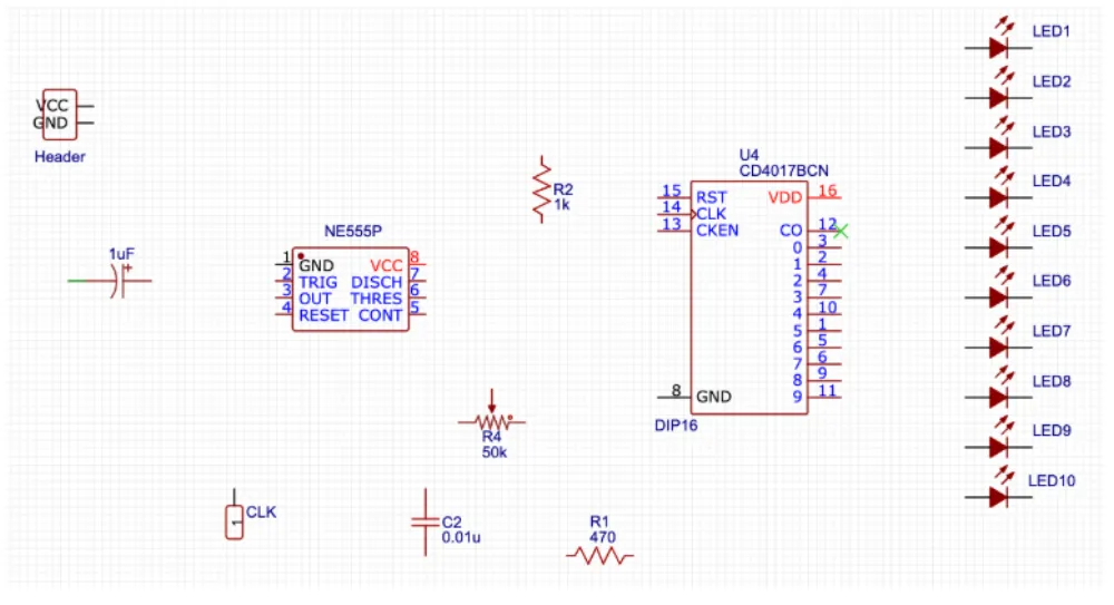
- Use 'R' to rotate components.
- Use Copy/Paste to create the 10 LEDs quickly.
- Remember to Save (Ctrl+S) often!
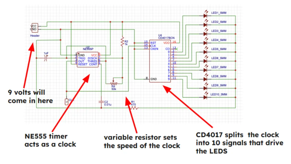
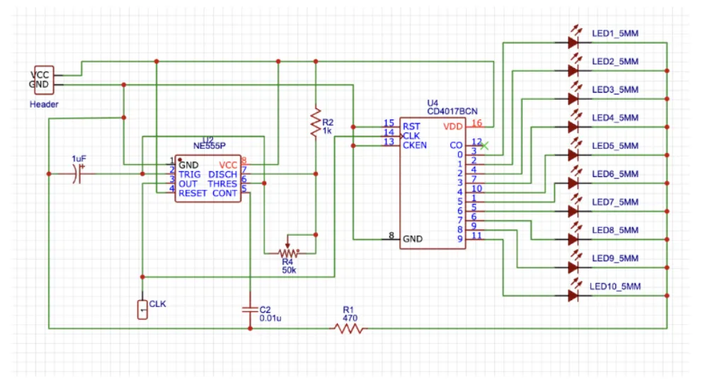
Wiring everything together
Connect your components following the diagram below. The little red dots indicate that two wires are connected. If wires cross without a dot, they are not connected.